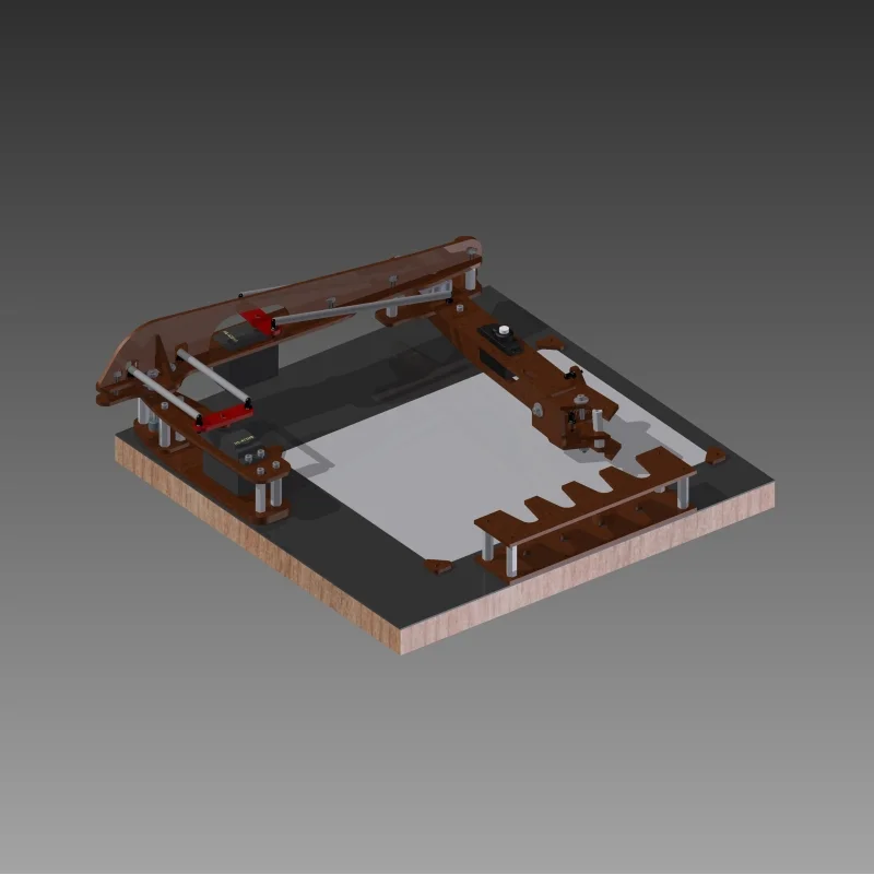
Robotic Drawing Arm - Part 2
I made a bit more progress on the arm today. I finished up the design for the pen gripper and the holder for multiple pens. So I think the two links of the arm are just about done.
To hold down the paper I designed four simple corner pieces that are held down with a bolt and spring. I can reach about 90% of the paper shown below with this design, so I'm pretty happy with that. I'll post dimensions of everything when I finalize the designs, but the paper shows is ~8"x10". Once I get into the programming, and depending on the actual rotation available in the servos, I might be able to get to every bit of the paper.
Top view. The grey tubes shown for linkage are just rough shapes. I'll be using threaded rod with ball end joints when I assemble.
Angle shot of the whole setup.
Here is a closeup of the gripper. I have two "fingers" that are stationary, and a third one in the center that is opened and closed by the small servo. The entire end of the arm is also hinged to allow the pen to be raised off the paper. I don't have the linkage modeled, but it will be flex cable.
Another view of the pen gripper angled up. The idea is that it will be able able to grab a pen from the rack, draw, and then place it back in the rack and grab another pen... The gripper is held closed by a small spring, so the servo does not have to work too hard to keep a grip.
This is the layout of all of the pieces so far to get cut. I'm still deciding on a material. I also need to work arranging the pieces for the smallest footprint.
I have a few other projects going on, so we'll see how much progress I make over the next few weeks on this.
I need to do some clash detection and make sure I get the full range of motion that I want and all the components are clear of each other. Another thing I need to do is a test assemble digitally, to make sure I can assemble it and have clearance to insert bolts, insert servos, etc. I've had issues in the past designing things to a very tight tolerance. The laser cutter can easily achieve that but the problem comes when the other components are not so exact. Servos have cords and grommets coming out of them, wood pieces might be warped, etc.
Hopefully I can get the pieces sent out to be laser cut, and then it will be simply putting it all together. Then I can really focus on the programming and electronic components of this project.
thanks for following along!
-G


